


GUIDE - Choosing the right gear ratio
GUIDE - Choosing the right gear ratio
Guide – Choosing the right gear ratio for a dry centrifical clutch (or torque converter - see notes).
When faced with gear choices such as sprockets on clutches and many different rear axle sprockets it’s not hard to become overwhelmed and confused – there really are a lot of choices.
To the uninitiated, new to the game, project builder or kart driver it can be a sea of numbers which, if chosen incorrectly, can result in either a top speed of virtually nothing at all, or in the worst situation a smoking destroyed clutch.
So the big question is: “What is the right gear ratio for me?”
Well, there are three factors that come into play when choosing a gear ratio. Before we go through those, it is important to understand how a dry clutch operates. If you haven’t already done-so, it’s worth reading through our clutch guide here: http://www.cutpriceracing.com.au/clutchcare
But if you don’t want to read that guide, here’s the excerpt that deals with how a clutch operates:
1. Dry Centrifugal Clutch operation
Learn how to install a Dry Clutch here: http://www.cutpriceracing.com.au/store/CLC-CCSC-GUIDE-Installing-Removing-Clutches/
Basic dry centrifugal clutches run a very simple method of power transfer. This makes them incredibly inexpensilve - one of their major pros. Both our popular entry level stock clutch (such as the CLC3512) and our GT clutch (such as the CGT3512) both emply this technology slightly differently, but the concepts are the same.
The clutch comprises of three main pieces:
- The outer drum (and drive sprocket)
The friction material & arrestor spring(s)
The transmission plate & central shaft. (central shaft not shown. Picture below shows friction material and spring installed)
In the picture above you can see the friction material installed onto the transmission plate.
You can see the transmission plate splines in the centre of the plate. The central shaft (not shown) slots into these splines and slides onto the crankshaft of the engine. It rotates with the engine because it is keyed and the key slots into the keyway on the crankshaft.
The drum sits over this material and is large enough so that the material does not contact the drum when it is fitted. You can rotate the drum freely when the unit is assembled as the friction material does not contact the drum.
As the speed of the crankshaft rotation increases (RPM increases) there is more and more centrifugal force on the friction material.
The spring holds them together in a tight circle and they do not touch the drum.
As the force pushing the friction material away from the centre increases to a point that it is greater than the force applied by the spring, the friction material starts to move outwards and contacts with the drum.
This begins to happen somewhere between 1500rpm and 1800rpm on the standard DRY CLUTCHES. At this point, the drum is still slipping on the friction material because the amount of force is not great enough to overcome the friction from the back wheels. The more weight, the more friction. When the drum slips, it creates heat. This is the biggest CON for the Dry Centrifugal Clutch.
NOTE: DRY CLUTCHES SHOULD NOT BE IDLED!
ONE MORE IMPORTANT THING TO NOTE IS THAT AFTER THE FIRST USE, SOME HEAT WILL INEVITABLY BE TRANSFERRED TO THE SPRING AND IT WILL STRETCH SLIGHTLY. FROM THIS POINT ON, AT IDLE, THE CLUTCH WILL SLOWLY BEGIN TO ENGAGE AT IDLE SPEED - THE HIGHER THE IDLE SPEED, THE MORE THE ENGAGEMENT WHICH WILL ACCELERATE WEAR.
At 2000rpm the friction material has so much centrifugal force applied to it that the spring can no longer arrest the material and it completely contacts the drum. This is considered it's FULLY ENGAGED rpm. Power is now transmitted directly through the chain to the rear drive sprocket and no further heat is created.
WHAT ARE THE FACTORS TO CONSIDER IN CHOOSING A GEAR RATIO?
#1 – Engine RPM working zone
Generally there are 3 main types of engines:
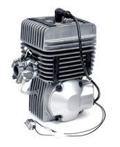
1. Two Stroke engines
Two stroke engines usually work from about 2000rpm through to 12,000rpm and higher.
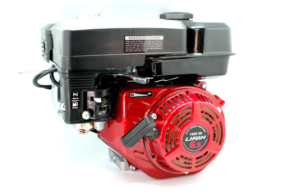
2. Four Stroke stationary engines (such as 6.5hp engines) stock setup
Four stroke governed engines usually work from about 1500rpm through to about 3500rpm.

3. Four Stroke stationary engines with governor removed
Four stroke engines without the governor will operate from about 1500rpm through to 5500rpm (average stock 6.5hp engine) or beyond depending on additional modifications and quality of the engine.
The golden rule with engine RPM working zones is that the wider the rpm range, the shorter gear ratio can be used which will achieve more acceleration with the same top speed.
#2 – Driven (usually rear) wheel diameter

There are a great deal of different size wheels available to choose from, some which are easy to install, and some which are difficult. It’s worth noting that very large wheels will cause headaches when trying to determine a good gear ratio because they will require a ratio in excess of the available sprockets.
The diameter of the rear wheel is determined by measuring from the bottom of the tyre to the top of the tyre (ie: the overall height of the tyre).
The golden rule is that the larger the driven wheels, the shorter the gear ratio required.
#3 – The intended use
While it might not seem all that important, the way the vehicle will be driven has a massive impact on the gear ratio required.
A vehicle that will be driven by children will require a much shorter ratio as they will generally be driving at lower speeds and a vehicle that is being raced (particularly in the case of speedway) will require a taller ratio to achieve a higher top speed as it will rarely see a low speed during use.
A vehicle being used for off-road purposes will require a shorter ratio as it will need maximum torque available at all times to negotiate terrain.
What needs to be considered here is how much torque/acceleration is required to negotiate terrain as well as who are the occupants, what is the frequency of stops and starts, and what sorts of top speeds will they be chasing.
a. Racing (home or sanctioned tracks)
When racing, you will most likely want a ratio that gives you the ideal road speed for the majority of the track. This could be completely different to the ratios suggested in the grid further down in the guide.
When racing, the ratio can be taller because stopping and starting occurs rarely. Ideally, keep the ratio short enough that the clutch stays engaged most of the way around the track – if the rpm drops below the engagement speed (approx. 2000rpm for a 4-stroke engine clutch) then you will be damaging the clutch.
b. Backyard
When using the vehicle in a medium sized backyard, space is confined and top speed will generally be low. The vehicle may be stopping frequently.
If the vehicle is being used to drift around (such as using slicks on a grass surface) then a lower ratio will work, but if the vehicle is being driven slowly then a short ratio will be required so that the engine is operated over 2000rpm for the maximum period of time).
c. Off Road
Off Road use will generally be a mixture of slow speed and navigating obstacles. This requires a very very short ratio in order to engage the clutch at minimum speed to ensure it doesn’t overheat, as well as provide maximum torque and acceleration to scale hills or rocks or to pull out of ditches and creek beds etc.
The basics - So what is a gear ratio?
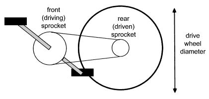
When you have a shaft (such as an engine crankshaft) that you would like to transfer the power from over to another shaft (a rear axle with fixed wheels attached) you generally need to use two sprockets and a chain.
The size of the first sprocket compared to the size of the second sprocket is the ratio. It’s usually noted as a fraction - the number of turns of the smaller sprocket required to turn the larger sprocket once.
The higher the number of turns of the drive sprocket required to turn the rear driven sprocket once, the ‘shorter’ the gear ratio is considered to be. Conversely, the smaller the number of turns of the drive sprocket required to turn the rear driven sprocket once, the ‘taller’ the gear ratio is considered to be.
For example, a 100mm sprocket on the output shaft, and a 100mm sprocket on the driven (rear axle) shaft gives a ratio of 1 turn to 1 turn – or 1:1. This would be considered a “Tall” ratio.
Similarly, a 100mm sprocket on the output shaft, and a 200mm sprocket on the driven shaft gives a ratio of 3 turns of the output shaft to 1 turn of the driven shaft – or 2:1. This would be considered a “Short”er ratio compared to 1:1.
With sprockets, for example, a 12T clutch sprocket (output shaft sprocket) driving a 60T rear axle sprocket gives a ratio of (60 divided by 12 = 5) 5 turns to 1 turn of the rear axle shaft – 5:1.
To determine your gear ratio, simply divide the rear axle sprocket by the clutch sprocket, so in the case of the above example, 60 divided by 12.
To determine a rear axle sprocket from a given gear ratio with a given clutch sprocket teeth number, simply multiply the first number of the ratio by the clutch sprocket teeth number (is: 5 x 12 = 60).
To determine a clutch sprocket teeth number from a given gear ratio with a given rear axle sprocket teeth number, simply divide the rear axle sprocket teeth number by the first number in the ratio (ie: 60 divided by 5 = 12) to give 12T.
How does PITCH affect gear ratios?
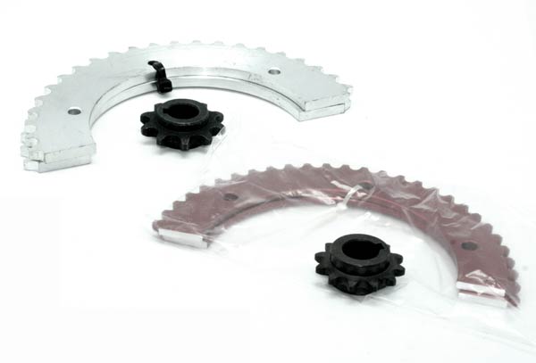
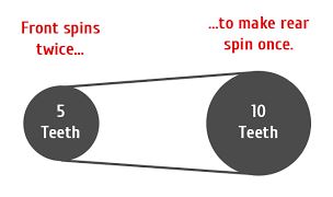
The picture above shows two different pitches which are the same ratio - notice both the small sprockets are the same diameter and both the large sprockets are the same diameter.
Interestingly, pitch does not affect the ratio or the ratio available for use (unless different size sprockets are available). Because the ratio is size dependant, a larger pitch will have less teeth for the same given diameter. The same reduction of teeth will occur on the rear sprocket such that the ratio is the same.
For example, a #35 pitch sprocket with a diameter where the inside of the teeth is 32mm has 12 teeth. A #420 pitch sprocket with approximately the same diameter has 10 teeth.
A #35 ptich 53T sprocket has approximately the same diameter as a #420 44T sprocket
For the #35 pitch, 53 divided by 12 = 4.4
And the #420 pitch, 44 divided by 10 = 4.4
So for any given size, the pitch will not change the outcome of the ratio.
So what ratio should I am for?
For those of you who would rather just skip to the end and find a suitable ratio, here’s a little cheat list of recommended ratios for each of the scenarios derived from the first section “What are the factors in choosing the right gear ratio”:
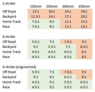
*FOR TORQUE CONVERTERS, YOU MAY REDUCE THE RATIO BY UP TO 40%. For example, for 300mm tyres and a 4-stroke (ungoverned) instead of 7.5:1 you can use a 40% reduced ratio of 4.5:1. Be aware that using the minimum recommended ratio will be the hardest on the equipment, so using a higher ratio than the minimum is best.
HOW DO I USE THE GRID?
*DISCLAIMER – IMPORTANT! While the grid above outlines sizes suitable, it does not mean they are ideal ratios. Sometimes the sprockets will not provide ground clearance, or they may be too tall to be gentle enough on the clutch for use resulting in a damaged clutch.
Just multiply the clutch teeth on the sprocket by the first digit in the gear ratio to get the best rear sprocket size.
For example, if you’re running standard 11x7.10-5 rear go kart slicks with an ungoverned 4-stroke and are using it for track and race purposes with a 12T #35 clutch, multiply 12 x 4.5 = 54T rear sprocket.
*Note: The red ratios show sprocket sizes that will either not be available to buy, or are larger than the rear wheel. Either way makes those unattainable with a standard clutch.
If you are going to require ratios in the red section, you will need to consider a Torque Converter. You can learn about Torque Converters by clicking here: http://www.cutpriceracing.com.au/store/Page59/
If you have very large wheels (Bigger than 400mm Diameter including tyre)
If you have very large wheels we recommend using both the Torque Converter AND an additional reduction jackshaft unit to ensure you are getting as short a ratio as possible. This little kt goes in-line between your torque converter or dry clutch to reduce the ratio by another 2 times - meaning you can run about a 6:1 reduction using a torque converter, allowing for the use of really big wheels. CLICK HERE TO FIND OUR 2:1 REDUCTION KITS