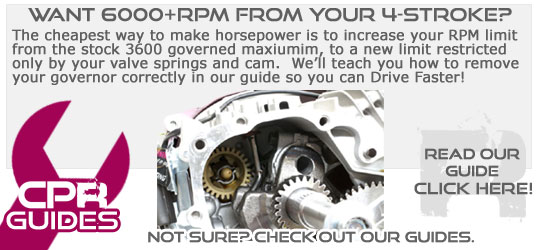
This guide is designed to provide information relating to removal of the governor from your GX200 or clone engine. Removing the factory governor will allow the engine to exceed the 3500rpm limit it was originally designed for. There is a risk of engine failure due to increased RPM, and dangerous catastrophic failure of the cast iron flywheel. We recommend only performing a governor removal if you understand the risks fully.
It is extremely wise to ensure you replace the stock flywheel with an aluminium one when removing a governor from a stationary 4-stroke engine.
We recommend buying the CPR Upgrade Kit (CLICK HERE) which makes the process easier by including additional parts required to complete the removal process (bungs and new throttle linkage system)
Foillowing is a step-by-step guide to removing the governor. The guide is complete, but may differ from engine to engine. This guide was designed to suit our CPR 6.5hp engine range.
Steps:
1. Remove Fuel Tank
2. Remove Throttle Linkage system
3. Remove Side Cover bolts
4. Remove Side Cover
5. Remove Side Cover
6. Align Governor Arm for Removal
7. Remove Governor Retainer Clip
8. Remove Governor Arm
9. Plug Governor Arm Hole
10. Remove Governor Hat
11. Remove Governor Retainer Circlip
12. Remove Governor Assembly Rear Section & Washer
13. Check Timing & Re-Align camshaft & crankshaft
14. Re-Install Side Cover
15. Re-Install Side Cover Bolts
16. Torque Side Cover Bolts to correct specification
Step 1 - If your engine is standard, remove the fuel tank and muffler. This process is not documented in our guide but is very straight forward.
Step 2 - Remove the throttle linkage system by removing M6 bolt (shown in the picture below) and unclipping the long dark-coloured rod from the carburettor. Lift the assembly from the engine and place aside.
Step 3- Remove the 6x M8 bolts from the sidecover.
Step 4 - Slide the cover forward along the output shaft. If the sidecover does not easily pull away from the engine casing, use a thin metal ruler or a butter knife to carefully break the seal with the gasket. Try to avoid damaging the gasket. If the gasket is damaged, it is best to purchase and install one - they are less than $10 and available from our store.
Step 5 - Remove the side cover completely, making sure the cam stays located in the engine. If the cam slides out and disengages with the crankshaft, it can be pushed back home. If you need to do this, make sure you turn the crankshaft and the cam so that the hole in the crankshaft lines up with the hole in the camshaft.
Step 6 - Align the governor arm to facilitate removal. To do this, rotate the crankshaft so that the governor arm (the kinked metal lever that goes through the top of the casing and down into the crankcase, kinking left and over the plastic cog) will clear the weights on the crankshaft.
Step 7 - Remove the clip holding the governor arm.
Step 8 - Push the governor arm into the crankcase. You may need to rotate the crankshaft slightly to allow the lever to be pushed all the way in - use a small screwdriver to push the lever all the way.
Step 9 - Plug the hole left by the removal of the governor arm. There are many ways to plug the hole, but we find the most reliable way is to use one of our brake rod pins which fits the CPR hole perfectly. You can find the pins on our store here: http://www.cutpriceracing.com.au/store/Brake-Rod-Retainer-Pin-and-Split-Pin/
It is recommended to use a glue (like araldyte) or you can try a high temperature threadlock to hold the pin in place. The pin is a tight fit on it's own though.
Step 10 - Remove the hat from the governor. The hat can be easily pulled off the governor assembly with a pair of pliers (it will simply slide off). Remember to remove the washer as well.
Step 11 - Remove the retainer clip. The retainer clip is a small circlip at the base of the shaft of the governor assembly. You can see it in the following picture. To remove the clip, use two picks, bent at 90 degrees about 3-5mm from the tip. Push the picks in towards the rear of the circlip from each side and lever the circlip up. It will take some time but you will get it eventually. There are several videos on you-tube showing many different ways to remove the circlip but this method will offer the least risk of cracking your crank case.
Step 12 - Remove the governor assembly by sliding it off the shaft. Be careful and remove the washer hiding behind the governor assembly.
Step 13 - Double check the alignment of the crank and camshaft to ensure correct timing. Rotate the crankshaft so that the two holes (one in the crankshaft and one in the camshaft) meet.
Step 14 - Slide the side cover back over the crankshaft, being careful to make sure the camshaft locates inside the little depression in the sidecover. When it is correctly positioned the sidecover will slide back into place without effort and a little 'click' will tell you it's home.
Step 15- Install the 6x M8 bolts in the sidecover - tighten finger-tight.
Step 16 - Torque the bolts in a criss-cross pattern to the specification in our CPR engine bolt torque table found here: http://cutpriceracing.com.au/phpbb3/viewtopic.php?f=13&t=803


