Home
::
STACP# Project Stub Axle Installation Guide


STACP# Project Stub Axle Installation Guide
STACP# Project Stub Axle Installation Guide
Guide – Installing our Project stub axle kits
Recently, one of my customers asked me how they should go about mounting the brackets in our project stub axle kits. This guide is designed to help provide a starting point for kart steering setup. The guide will describe where and how the C section stub brackets should be located so that they are welded in position at the optimum locations.
This guide is written with the intention to allow you to install your stubs without a great deal of technical knowledge. For those of you who would like to understand more, we have included a basic guide to the steering geometry. Installation is outlined in 3 simple separate stages comprising of the kit contents, positioning the C clamps, and fitting the stub axles. Please see our steering guide for correct measurement and sizing of tie rods as well as how to fit the steering assembly.
So that we could get this guide to you quickly, I have borrowed some information from a site online which explains things more comprehensively than I could.
CONTENTS
1. Introduction
a. Castor Explained
b. Camber Explained
c. Toe-in Explained
d. Ackerman Effect Explained
e. King Pin Inclination Explained
2. Our Project Kit Contents
3. Positioning the C clamp brackets on the chassis
4. Fitting the stub axles to the C clamps
5. Tuning
1. INTRODUCTION
Understanding go kart steering geometry. (from DIYGokarts.com)
Understanding Caster, Camber, Toe, and Ackerman
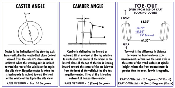
1a. Caster Explained
To understand caster you need to picture an imaginary line that runs from through the upper ball joint and extends through the lower ball joint. From the side view the imaginary line will tilt forward or backward. The tilting of this imaginary line is defined as caster.
Caster is measured in degrees by using a caster camber gauge. If the imaginary line described above tilts towards the back of the car, at the top, then you will have positive caster. If the imaginary line tilts forward then you would have negative caster.
Positive caster provides the directional stability in your race car. Too much positive caster will make the steering effort difficult. Power steering will allow you to run more positive caster. Negative caster requires less steering effort but can cause the car to wander down the straightaway.
1b. Camber Explained
Camber is the tilt of the tire as viewed from the front of the car. If the top of the tires lean toward the center of the car then you have negative camber. If the top of the tire tilts out away from the center of the car then you have positive camber.
Camber is measured with a caster camber gauge and is usually easily adjusted with shims or adjustable upper a -arms. Always check the toe when making camber or caster adjustments.
1c. Toe - In Explained
Toe is the pointing in or pointing out of the front wheels as viewed from the top of the car. If the front wheels point in, toward the front of the car, at the front edge of the wheels then you have toe in. If the front wheels point out at the front edge then you have toe out.
In general, dune buggies and race cars are set with a small amount of toe out. The toe out provides directional stability. Toe out pulls on the tie rods taking out the tiny clearances that are built into the tie rod ends. Depending on the type of car typical toe readings are 1/16" to 1/4" out for tracks under 1/2 mile in length.
Toe can be set with a tape measure on the side walls of the tires. A tape is placed on the inside front of the tire as near the rim as possible or pick a good location on the tire tread if possible! (As close to center horizontal as possible) and then measured in the same location on the front edge of the other front tire. Remember to measure from the same locations each time you check the toe. Now check the rear side of the front tires as close to the center rear of the tires as possible. If this number is a smaller tape reading on the back edge this indicates toe out.
For a very precise reading you can scribe a line in each front tire. Use a tire scribe and spin each of the front tires to get your straight line. You can then measure between the two scribed lines with a tape measure or with a toe bar or with toe plates, a smaller measurement at the backside of the tire again, indicates toe out.
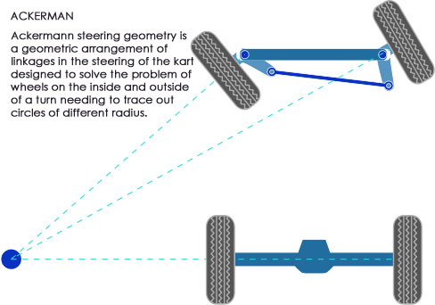
1d. Ackerman Effect Explained
Ackerman is the difference in turn radius between the front tires. On oval track cars it can be desirable to create a situation where the left front tire turns faster than the right front tire. The Ackerman effect can help the car turn better through the center of the turn. You can measure the amount of Ackerman you currently have by using a set of turn plates. Typically, Ackerman is measured by turning the right front 10 degrees to the left. If you have Ackerman, the left front will travel further than the right front. A typical amount would be three degrees in 10 degrees of steering. To simplify, moving the right front from zero through 10 degrees of steering will cause the left front to move say 13 degrees in this scenario.
Ackerman is created by your front end geometry. Tie rods that angle forward from the inner pivot point out to the spindle will have more Ackerman.
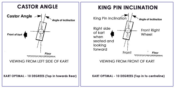
1e. KPI- or King Pin Inclination Explained.
Ideally, you should be able to draw an imaginary line right thru the middle of your kingpin, and where that line hits the road should be the centre of your tire's contact patch. Setting up a kingpin angle generally involves welding your spindle brackets to your frame inclined at an appropriate angle (often, close to 10*). Then, your spindles get welded to the steering knuckles at the opposite angle. The result is this- With the wheels steered straight, the wheel is perpendicular to the road. As you steer, that KPI angle is altered by your caster angle, which helps you steer by loading up the inside front wheel while cornering.
2. Project Stub Axle Kit Contents
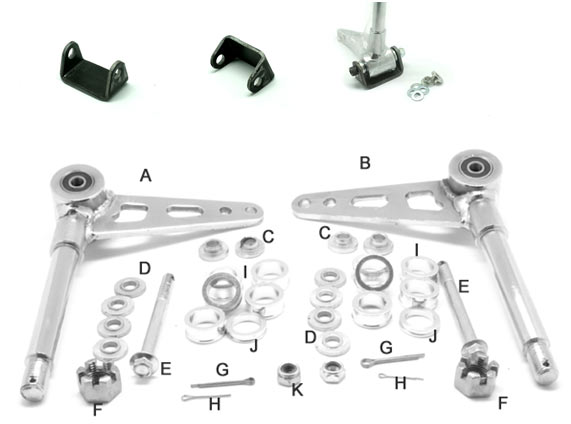
A – 1x Stub Axle / Spindle Unit (Left Side)
B – 1x Stub Axle / Spindle Unit (Right Side)
C – 4x Long 12mm to 8mm reducers (insert into chassis bracket/mount)
D – 8x Short 12mm to 8mm reducers (spacers between spindle and bracket) or 4x reducers and 12 machine washers or 0x reducers and 24 machine washers
E – 2x Kingpin bolt - M8 x 90mm zinc plated hi-tensile hex head bolt
F – 2x Wheel Retainer Nut (M14 Fine Castle Nut or Nyloc Nut)
G – 2x Large Castle Nut Split Pin (Not supplied if using Nyloc)
H – 2x Small King Pin retainer Nyloc Split Pin
I – 10x 10mm Wheel Spacer Washer
J – 2 x 5mm Wheel Spacer Washer
K – 2x M8 Nyloc King Pin Retainer Nut
L – 2x C Clamp Bracket
*Note: Contents may differ slightly from pack to pack due to stock availability
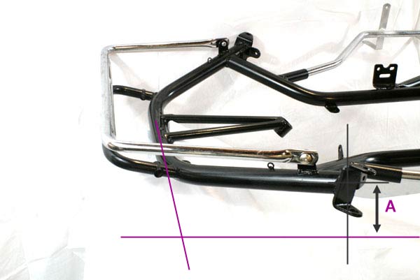
3. Positioning the C clamp brackets on the chassis
When positioning the C Clamps on the chassis, try to achieve a position as close to the optimal castor and king pin inclination settings as possible (10 degrees & 10 degrees – see pictures in the INTRODUCTION marked Castor and King Pin Inclination).
For a race kart, the C clamp centre should be approximately 85mm from the bottom of the floor (Dimension A). Ideally, build these dimensions into your tube work to make your steering set up easier.
4. Fitting the stub axles to the C clamps
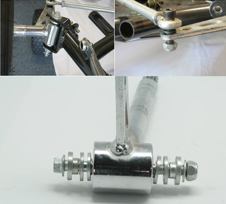
a. Ensure the stub axles/spindles are located the correct side. When fitted correctly, the flat bracket should face rearward and slightly downward. The Stub Axles should be horizontal.
b. Fit two 10mm-8mm spacers to the C-Clamps (Ackerman points) from the outside of the clamp.
c. Fit the M8 Kingpin through the top of the clamp, then fit two spacers (flat side butted up against each other), then the stub axle, then two more spacers (flat side butted up against each other) then push the kingpin through the bottom clamp and reducer, fit an M8 washer.
d. Fit the nyloc and then split pin.
e. Fit the two steering stop bolts (M8 Hex Head bolts with adjustment nuts) to the two brackets to the rear of the Ackerman point (C Clamp) which holds the spindle/stub axle in place.
5. Tuning
Base starting points for Caster, Camber, King Pin Inclination, and Toe In/Out
Caster can safely set around 10 degrees up to about 15 degrees
Camber can safely be set at 0 degrees
King Pin Inclination – 10 degrees is optimal – for off road and recreational karts, good results can be obtained at 0 degrees.
Toe In/Out should be set at 0 degrees to provide optimum straight line speed, but if speed is not critical, set Toe Out minimally (say 2 degrees) to provide more straight line stability.
KPI- or King Pin Inclination. Ideally, you should be able to draw an imaginary line right thru the middle of your kingpin, and where that line hits the road should be the centre of your tire's contact patch. Setting up a kingpin angle generally involves welding your spindle brackets to your frame inclined at an appropriate angle (often, close to 10*). Then, your spindles get welded to the steering knuckles at the opposite angle. The result is this- With the wheels steered straight, the wheel is perpendicular to the road. As you steer, that KPI angle is altered by your caster angle, which helps you steer by loading up the inside front wheel while cornering.
Need Help?

Gift Certificates

Categories
Bestsellers

Special
My Shopping Cart
My Shopping Cart
Cart is empty
My Account
Free Same-Day Dispatch!


Product Updates via Facebook

Get notified about our holiday times

We Accept Paypal

Outstanding Service!